CONNECTION SERIES
Development Visual BASIC
This program makes it possible to test a connection series on the PC.
The program
This program makes it possible to test a connection series. It uses a DLL MSCOMM.DLL. Allows to send on the port chains of caratères, a file...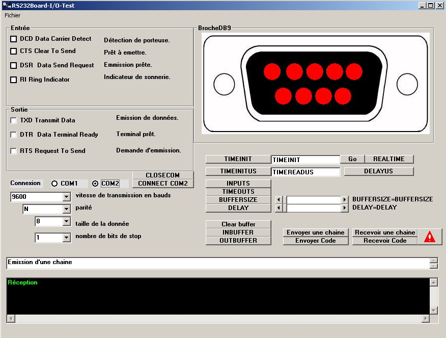
The port series
The port series, even if it is less and less used today, it remains still a standard, in particular in industry.
Synopsis
1. Stitching and performances
2. Material protocol
3. Protocol XON/XOFF
Stitching and performances
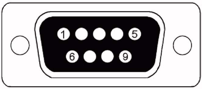
Each computer has two ports series. They take the shape of two plug connectors with 9 pins (for the PC a little older, one of both has 25 pins), named out of standard COM1 and COM2. The diagram opposite shows stitching. To the origin, the port series was intended to be connected to a modem, it is from there that the name of the pins are drawn. Indeed, only three pins are necessary to communicate with a peripheral (TxD, RxD and mass), the other pins being only signals of control and state. The port series is very well protected from the short-circuits (with an intensity from 20mA) and them pins are limited while running. Thus, it is completely possible to feed a small electronic assembly (for example the mice series are fed by line RTS) but it is nevertheless preferable to have resorts to an external food. Catch DB9 seen of front.
Stitch |
E/S |
Designation |
Description |
1 |
Entry |
DCD (Dated Detect Carrier) |
Detection of carrying. |
2 |
Entry |
RXD or RD (Receive Dated) |
Reception of data. |
3 |
Exit |
TXD or TD (Request Dated) |
Emission of data. |
4 |
Exit |
DTR (Final Ready Dated) |
Ready terminal. |
5 |
- |
GND (Ground) |
Mass. |
6 |
Entry |
DSR (Set Ready Dated) |
Ready Emmission. |
7 |
Exit |
RTS (Request To Send) |
Ask emmission. |
8 |
Entry |
CTS (Clear To Send) |
Loan with emettre. |
9 |
Entry |
IH (Indicator Boxing ring) |
Indicator of ringing. |
With the parallel port, all the signals are transmitted the ones beside the others in a cable which very often takes the form of a tablecloth. This process is fast but it is noticed that the parallelization very close wire armature between them a capacity coupling.
To reduce this effect, it is possible to intercalate wire connected to the mass between wire conveying the signals.
Moreover, one cable represents a considerable load and it is very often useful to have recourse to circuits buffers to provide more power.
Thus, over big lengths, the tension can fall at the point not to correspond more to logic TTL (0-5V).
There the port series draws its pin from the play: in the protocol of communication RS232C, the data are transmitted in series (thus on only one wire) with a higher gauge of tension (-12V/+12V).
However a transmitter of the computer type, and a receiver such as for example a numerical director of commade, function at very different speeds. Receiver has thus buffer memory (a buffer whose size is of one or more screens), being able to receive information at the rate/rhythm of the transmission.
It is thus advisable to manage two cases: the saturation of the buffer and its availability. For that one will use what one call a communications protocol allowing to manage the sending and the saturation of the buffer.
Material protocol
It is by this standard that it is possible for you to connect two computers together (direct connection by cable under Windows), or to communicate with a modem, printing etc. This protocol is known as full duplex because it can transmit data and receive some at the same time, via the lines RxD and TxD.
It is completely possible to use only these two terminals in more of the mass (for the reference), while taking care of course to connect the TxD terminal of the first computer to the RxD pin of the second and vice versa.
The control of the data flow will be then completely software because the additional terminals of the port are not used. With this protocotle the equipment in reception, when its buffer is almost full, informs the transmitter by decontaminating signal RTS; when the buffer is again ready to receive data, it reactivates this line; the transmitter receives this information on its line CTS.
Software protocol
Software management is controlled by the emission of control characters:
- Xon, DC1 of hexadecimal value 11 which indicates that the receiver can receive data because its buffer is not full;
- Xoff, DC3 of hexadecimal value 13 which indicates that the receiver cannot receive data because its buffer is almost full.
Whereas material management is reserved for the only connection null modem between two GCV, software management can take place with an unspecified model of transmission. The control characters coming from the receiver function exactly, with respect to the transmitter, like signal RTS.
However, the analysis being carried out in a software way, the rate/rhythm of the transactions is less powerful than for material management. Moreover, the transmission is necessarily full duplex.
Links
Nothing for the moment.
Thank you to send your comments, bug carryforwards and others with: usinage5axes@free.fr
|
|